





A state-of-the-art foot control is more than just a switching contact
Whether in the operating theatre, radiology or treatment rooms: medical foot switches and hand controls must transmit their signals quickly, precisely and reliably. At the same time, the latest medical devices make high demands on the exchange of control, status and system data, as well as the integration of different control elements.
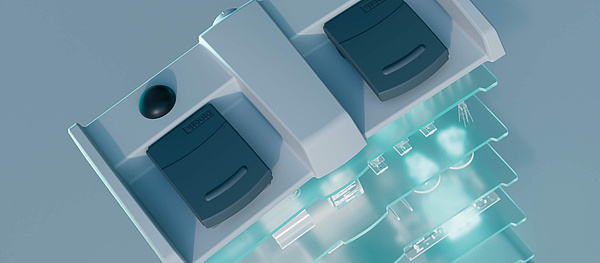
For these requirements, steute Meditec has developed the steute MED Framework (SMF). This modular communication platform connects your medical device with medical user interfaces from steute, enabling customised, bidirectional data exchange – via cable or remote control.

Next-generation communication
Classic cabled foot switches transmit switching signals directly to the medical device. With the tried-and-tested SW2.4 LE wireless solution from steute, the signals are sent remotely to a receiver which then processes and forwards them to the medical device.
SMF expands on this principle: instead of simply transmitting switching signals in one direction, the foot switch and the medical device can now exchange information in both directions. In the SMF2.4 wireless variant, the receiver passes on the data from the foot switch without functional interpretation. Evaluation of the data and any resulting call to action remain with your medical device.
If your risk analysis demands it, a back-up cable can be connected between the foot switch and the receiver. With cabled SMF variants, data exchange has the same format. Your medical device is therefore able to process the information with the same logic, independently of how it was transmitted. This simplifies integration and permits flexibility when choosing between cabled and wireless solutions.
Cybersecurity, upgradability and technical changes across the product life cycle are all accommodated by design from the outset. The result is a shared communication basis for existing and future product generations.
Your benefits in detail

SMF in practice: transparent information transfer.
Typical use case: detection of user interface anomaly
If a foot switch slides off its platform in the operating theatre, an integrated position sensor detects the resulting slope. If the operational concept stipulates for such cases an immediate block, the medical device will receive a notification and the command will not be executed.
With SMF, all available signal, status and error information is sent to the medical device. It can link the incoming data to the detected anomaly and communicate potential misuse accordingly.
The medical device then reacts in line with the pre-determined and validated operational and safety concept. Depending on the risk evaluation, the reaction can be, for example:
- the entered command is rejected, or the function in question is blocked;
- further operation, possibly restricted, is still permitted if it is allowed in the safety concept and has been assured by the risk evaluation.
Decision-making authority over how the system reacts remains with the medical device. The operator can be informed whether a command has been accepted, rejected or processed with restrictions. This supports traceable system reaction and transparent user guidance. Management of missing data is also described within the customised safety concept.
Clear roles. Defined data exchange.

Actuation

Transmission
Decision

Feedback
SMF – Developed for sophisticated medical products – your technical benefits
Multipoint communication: multiple controls, a single receiver
More system architecture flexibility through shared connection for multiple controls.- Connection for multiple controls: Up to five foot switches or other controls can communicate with a shared receiver inside the medical device.
- Hardware reduction: Fewer receivers and interfaces simplify integration.
- Creation of a flexible architecture: Different device and system configurations can be realised on a uniform wireless platform. Participant quantity and allocation are agreed in line with the specific project.
Your benefit: More system architecture flexibility through shared connection for multiple controls.
Customised data transfer
You use the data specifically required by your application. Your medical device retains control over evaluation of the data and any resulting reactions.- Customised data use: The user interface provides status information and data via predefined services. The medical device subscribes to the services it requires.
- Variable data transfer: Variable data contents and lengths can be flexibly reproduced.
- Data prioritisation: Relevant operating signals can be prioritised for transmission.
- Energy savings: Customised data transfer reduces communication traffic and supports energy efficiency.
- Differentiated evaluation of status data: Not only operational signals are transmitted, but also appropriate status and error data.
- Specific reaction to errors: In accordance with its risk assessment and safety architecture, the medical device reacts with a warning, restricted further operation or cancellation.
Your benefit: You use the data specifically required by your application. Your medical device retains control over evaluation of the data and any resulting reactions.
Flexible and uniform interfaces
You select the connection suitable for your device architecture and are able to integrate both cabled and wireless variants on a shared communication platform.- Simpler integration of variants: Cabled and wireless solutions use a shared data model with uniform interpretation of transferred information.
- Selection of suitable interfaces: The connection is adapted to your device architecture, for example via established serial interfaces.
- Use of existing wireless technology: A suitable existing wireless interface can be integrated in a specific project. An additional wireless receiver may then be superfluous, provided that the technical requirements are fulfilled.
Consideration of required integration effort: Direct integration requires specialist knowledge from the customer regarding timing, connection management and troubleshooting.
Your benefit: You select the connection suitable for your device architecture and are able to integrate both cabled and wireless variants on a shared communication platform.
SMF wireless technology
Short reaction times, flexible data transfer and energy-saving operation.- Short reaction times: In a reference configuration, the mean radio latency for digital signals is around 12 ms.
- Efficient transmission: Connection intervals of 7.5 ms and a gross data rate along the transmission path of up to 2 Mbit/s provide the technical basis for short reaction times.
- Checking of data integrity: Checksums and packet counters support detection of corrupted data packets and packet loss.
- Reduced power consumption: Customised communication and energy-saving features support longer operating times in conjunction with appropriate system configuration.
- Additional flexibility with back-up cable: For special use cases, a cabled communication option is also available. Connecting the foot switch to the receiver via the back-up cable enables seamless communication via the cable interface.
Your benefit: Short reaction times, flexible data transfer and energy-saving operation.
Modular software and hardware framework
You gain an expandable platform in place of an inflexible one-off solution – the basis for scaled-back development, testing and adaptation.- Flexible hardware adaptation: A consistent layer model decouples functional logic and the data model from the hardware.
- Reduced dependency on components: Internal components can be replaced as required, without the superordinate application logic needing complete redevelopment.
- Reusable modules: Reusable modules simplify adaptation, expansion and testing.
- Long-term platform use: The service structure is designed to facilitate further use of existing SMF functions following expansion. New features can be added step by step.
- Efficient verification: Automated tests and hardware-in-the-loop tests support reproducible, consistent verification within the development process.
- Traceable integration: Structured and machine-readable documentation supports integration, checking and traceability.
Your benefit: You gain an expandable platform in place of an inflexible one-off solution – the basis for scaled-back development, testing and adaptation.
Integrated cybersecurity and updatability
Specific software component updates and cybersecurity support across the complete product life cycle.- Cybersecurity by design: Security requirements are agreed in line with IEC 81001-5-1 at an early stage in the development process.
- Specific updating of components: Firmware updates for integrated SMF components can be inputted via the medical device.
- Reaction to new requirements: Component-based updatability supports the implementation of security updates.
- Specific test planning: Component-based updates facilitate change demarcation. The required extent of testing and validation depends on overall system impact.
- Vulnerability monitoring: On the basis of an SBOM in CycloneDX format, implemented software components can be automatically monitored for new CVE – for early detection and evaluation of security risks.
Your benefit: Specific software component updates and cybersecurity support across the complete product life cycle.

steute Test Framework – Automated testing. Transparent development.
Immediate testing of software modifications and transparent documentation of all results: the steute Test Framework supports the development of SMF-based user interface solutions through automated testing and direct linking of the test results with software requirements.
Core feature Continuous Integration (CI).
An automated pipeline builds the software from the source code, conducts statistical code analyses and unit tests, and then tests the software on the target hardware in the Hardware-in-the-Loop (HIL) test rig. Developers receive rapid feedback about all implementations and their test results.
The pipeline consolidates all results in a test report, linking them via clear requirement identifiers with the software requirements. This automatically creates a traceability matrix transparently linking the requirements with the corresponding test results.
Automation as an integral part of development
Overnight software builds and HIL tests are an integral part of all development projects, as are automated statistical code analyses, including to MISRA-C:2012. Automated unit tests check individual software components and capture the code blocks covered by the tests. Software bills of materials (SBOMs) are also created automatically. Participating CI services are run in Germany on servers belonging to steute.
Your benefits:
- Immediate evaluation of software modifications: Automated testing provides rapid feedback and supports detection of errors during the development process.
- Testing on target hardware: HIL testing complements statistical code analyses and unit tests on the hardware actually used.
- Transparent verification and documentation: Automated consolidation of test reports and traceability matrices creates a structured basis for software verification and technical documentation.

Technology, documentation and project-specific support
SMF is the technology underlying a steute user interface solution. All necessary components, interfaces, data and requirements will be agreed and implemented together in a joint development project.
For integration purposes, we will provide you with agreed project-specific documentation and support:
- Interface description, data model and integration instructions.
- Traceability of requirements and tests for the agreed scope of the project.
- Software bill of materials (SBOM) and security documents, e.g. threat and joint risk analyses.
- Customised tests in accordance with your specifications.
- Additionally agreed update and life cycle support.
Implement SMF – with the right foot switch for your application
Together we will find the right foot switch with SMF-based user interface solution for your application. This also holds for new customised foot switch developments. The specific SMF version and integration will be discussed and agreed as part of the project.


